The controls you need
Define the PLC, HMI, I/O, networking and software scope around your process rather than assuming one architecture fits every application.
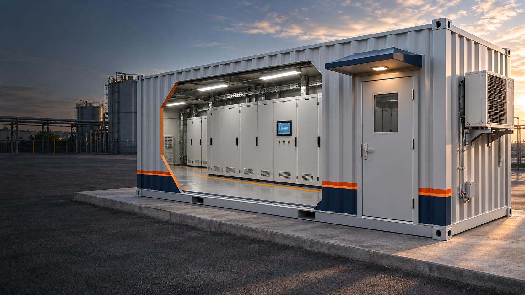
An insulated high-cube container brings the controls, drives, climate systems and utility power together in a compact, transportable package.
The reference design uses a 20-foot high-cube ISO container, giving the automation a dedicated, finished environment. Equipment layout, working space and access are coordinated before the build.
Concept artwork. Final layout follows your approved design.A coordinated installation from the container shell to the electrical equipment.
Reference configuration. These features summarize the supplied 20-foot design basis. Final loads, equipment quantities, HVAC capacity, electrical ratings and included services are confirmed in the project proposal.
Equipment heat, site temperature and the required availability shape the climate-control design. Lead/lag and redundant arrangements can be specified with the capacity and operating sequence your process needs.
Define the PLC, HMI, I/O, networking and software scope around your process rather than assuming one architecture fits every application.
Equipment mounting, internal wiring, protected cable routes and terminations are planned as part of the complete assembly.
Agree incoming power, grounding, field cable entries, offloading and startup responsibilities before the system is dispatched.
The reference configuration combines an insulated high-cube container, a finished interior, personnel access, LED lighting, dual industrial HVAC, utility power distribution, protected internal wiring, a main control panel and Allen-Bradley drive integration. Your proposal identifies the exact included equipment and services.
Lead/lag HVAC and redundant arrangements can be specified. Controller, network, control-power and cooling redundancy address different failures, so we agree the required behavior and capacity for each system. The reference thermal arrangement is a design basis, not a universal N+1 guarantee.
The proposal assigns each responsibility. Transport can be coordinated with the project, while crane access, offloading, foundations, field terminations and commissioning are confirmed with you and your site team. This keeps delivery aligned with a prepared location.